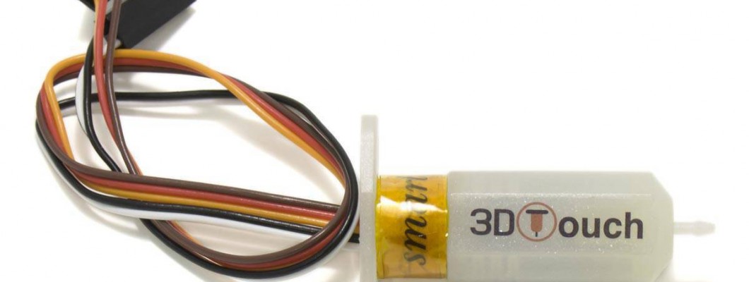
3DTouch is an automatic leveling system for 3D printers that can measure the inclinations or variations of the printing surface in a precise and simple way.
It is compatible with any type of surface: glass, metal, etc. since, unlike other systems, it works by contact, which is a great advantage over other capacitive, inductive and other sensors.
This device has a probe that collects the position data different points of the printing surface, so that it can calculate the deviations and correct it during printing.
In this post we will explain each step necessary to configure the sensor using Marlin and Ramps board. Mention that there are multiple options for the configuration of this sensor, we will explain what we are using and consider most useful.
Main functions:
- It works as if it were composed of an RC servo and a micro switch.
- Small, lightweight and easy to assemble.
- Self-test when turned on: the pin acts twice, so that if there is something that prevents the free movement of the probe, a flashing red light will be displayed.
- LED alarm: if it finds a problem during its operation the light will flash.
- High precision, 0.005mm.
- Great versatility in the sampling configuration.
Assembly
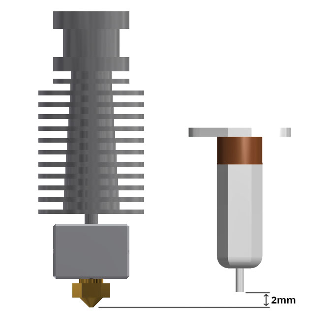
Depending on each extruder, it can be mounted using different parts that adapt it, but it must always be installed perpendicular to the surface.
In a correct assembly, the height of the contracted probe should be about 2mm above the height of the nozzle.
If you are going to assemble in our P3steel of an extruder, you can use this piece that adapts it shared in thingiverse.com:
https://www.thingiverse.com/thing:3403967
Caution
It is important to test the sensor well before homing or leveling the platform. Incorrect placement or installation can damage the printer.
Electronic connections
3DTouch has two connections, one corresponds to the limit switch function of Z and the other to the self-leveling function.
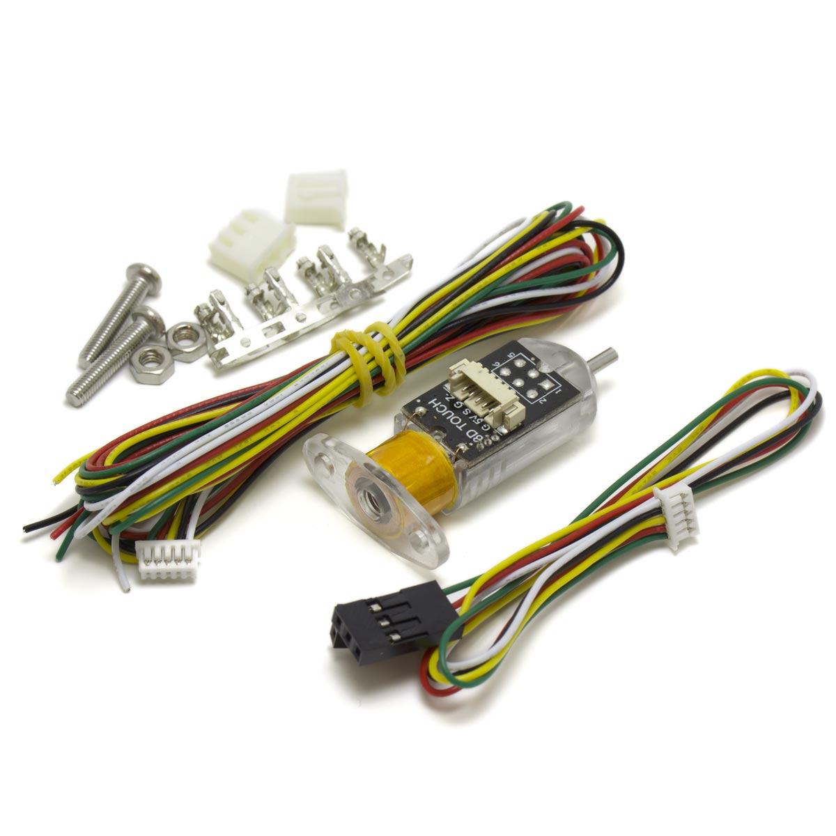
To make the connections, just for each cable or line we have to prepare the cable with the supplied dupont connector.
The connection in the Ramps is the following:
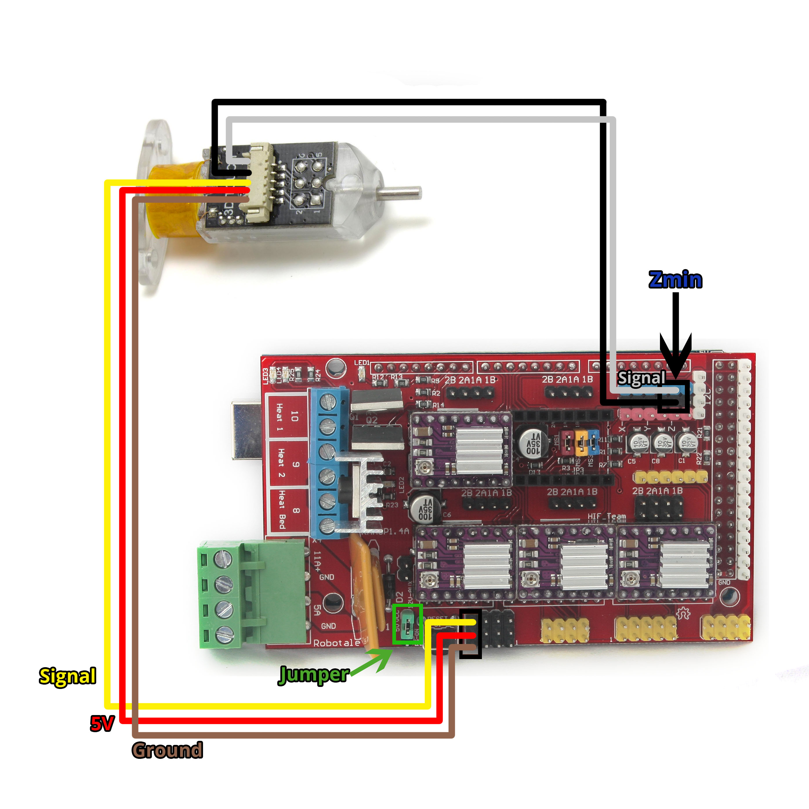
As we can see, the black and white cable (signal) is connected in the position of the limit switch of Zmin.
The other cable is connected in the Servo position, with the order of the scheme (Signal, 5V, Ground). In addition, you have to place a jumper to reach the 5V.
Modifications Marlin Firmware
We have to upload the firmware again with the configuration for our 3DTouch.
To configure the sensor we must modify Marlin Configuration.h:
Ensure that the Zmin endstop is enabled:
| #define USE_ZMIN_PLUG |
Enable the line that assigns the sensor PIN of the limit switch Zmin to the 3DTouch sensor, in this way the sensor will also be the limit switch Zmin:
| #define Z_MIN_PROBE_USES_Z_MIN_ENDSTOP_PIN |
Now we start with the 3DTouch configuration. We will put the lines that we recommend to activate with the values that we recommend as an example or starting point, depending on the printer that is installed, you may need other values, these are only reference values:
We enable the BLTouch sensor (equivalent to 3DTouch):
| #define BLTOUCH |
In this line we choose the time it will last to take the reading since the probe is out, we have set 50 milliseconds. If the sensor becomes dirty or stops working properly, we can modify this value:
| #define BLTOUCH_DELAY 50 // (ms) Enable and increase if needed |
Lines to place our 3Dtouch regarding our nozzle:
| define X_PROBE_OFFSET_FROM_EXTRUDER 22 // X offset: -left +right [of the nozzle] #define Y_PROBE_OFFSET_FROM_EXTRUDER 0 // Y offset: -front +behind [the nozzle] #define Z_PROBE_OFFSET_FROM_EXTRUDER 0 // Z offset: -below +above [the nozzle] |
In this example case, the sensor will be 22mm to the right of the nozzle, for each printer model it will be different.
In the following lines we assign how much we want the probe to contract depending on when it is performing the sampling:
| #define Z_CLEARANCE_DEPLOY_PROBE 9 // Distance in mm that the probe deploys or stows in a first sampling #define Z_CLEARANCE_BETWEEN_PROBES 6 // Distance in mm that the probe deploys or stows between different sampling points #define Z_CLEARANCE_MULTI_PROBE 3 // Distance in mm that deploys or stows the probe in different measurements from the same sampling point (when enabled) #define Z_AFTER_PROBING 5 // Distance in mm in which the probe remains with respect to the printing surface after sampling |
We choose the type of sampling we want: Bilinear:
| //#define AUTO_BED_LEVELING_3POINT //#define AUTO_BED_LEVELING_LINEAR #define AUTO_BED_LEVELING_BILINEAR //#define AUTO_BED_LEVELING_UBL //#define MESH_BED_LEVELING |
We choose the number of points we want for sampling, in this case 9:
| #define GRID_MAX_POINTS_X 3 #define GRID_MAX_POINTS_Y GRID_MAX_POINTS_X |
In these lines, we set the limits for sampling, so that you do not make the measurement on the outside of the printing surface, where you can find, for example, clamps that hold the glass:
| #define LEFT_PROBE_BED_POSITION 25 #define RIGHT_PROBE_BED_POSITION 175 #define FRONT_PROBE_BED_POSITION 25 #define BACK_PROBE_BED_POSITION 175 |
To make Z Safe Home, which is, checking the position 0 of the Z axis in the center of the printing surface, we must enable the following lines:
| #define Z_SAFE_HOMING #if ENABLED(Z_SAFE_HOMING) #define Z_SAFE_HOMING_X_POINT ((X_MIN_POS + X_MAX_POS) / 2) // X point for Z homing when homing all axis (G28). #define Z_SAFE_HOMING_Y_POINT ((Y_MIN_POS + Y_MAX_POS) / 2) // Y point for Z homing when homing all axis (G28). #endif |
Optionally, we can enable a fast function for Babystepping or Z Offset. By enabling this line, we can access this function by pressing twice on the LCD potentiometer. We see it in Configuration_adv.h:
| #define DOUBLECLICK_FOR_Z_BABYSTEPPING // Double-click on the Status Screen for Z |
Add in gcode
We have to add certain commands to our gcodes to execute the leveling correctly:
| G28 ; global home G29; platforma leveling G1 Z5 F5000 ; lift nozzle G1 X-10 Y100 Z3 F5000; avoid clamps or clips |
With these codes, you will perform a Home and perform self-leveling before you start printing.
For more information about these codes visit:
http://marlinfw.org/docs/gcode/G028.html
http://marlinfw.org/docs/gcode/G029-mbl.html
http://marlinfw.org/docs/gcode/G000-G001.html
Checking the Z offset
Once you start printing, we should see if the height of the nozzle with respect to the bed is correct.
If it is not, we must adjust the offsetin Z.
To do this, by pressing twice the potentiometer of the LCD, if we have activated this function, we enter the option of Z Offset, there we adjust the offset. And once the printing is finished we must Save in memory.



12 Comment(s)
Genial articulo y muy bien explicado!
Muchas gracias! =)
lo volveréis a tener en stock
Si, ya está en stock de nuevo :)
Por qué me viene con una resistencia el sensor? Gracias
Nuestro sensor no incluye ninguna resistencia externa.\r\nPor favor contacte con nosotros a través de: soporte@hta3d.com enviando el número de pedido y una foto de la duda para que podamos ver a lo que se refiere.
Lo puedo instalar en una artillery x1?
Este sensor se puede instalar muy fácilmente en cualquier impresora 3D, solo necesita la conexión de un servo y un final de carrera, y la mayoría de placas tienen estas conexiones disponibles.
He visto que en la artillery x1 se conecta en sustitución del lez, haciendo algún cambio de cableado en la placa, pero el Led tiene 4 pines y el 3d touch lleva 5 , se puede instalar? Quiero pediroslo y estar seguro q puedo instalarlo\r\nGracias
Las conexiones de este sensor son muy simples, es equivalente a un servo + un final de carrera, por lo que se puede instalar en la mayoría de impresoras 3D, pero no te puedo confirmar si en ese modelo concreto hay alguna incompatibilidad.
Muy buenas, voy a instalar este nivelador en mi P3steel con placa ramps 1.6+ y mi duda es donde colocar el jump para suministrar los cinco voltios, ya que en el ejemplo es una ramps 1.4.\r\nAdemás, ¿sería recomendable hacer alguna otra configuración en Marlin además de los parámetros indicados aquí. El firmware me lo he descargado de vuestra página para la P3steel 2.0.6.1?\r\nPor último, he visto que hay una nueva versión 2.0.7.2, ¿es una versión estable?\r\nMuchas gracias de antemano.\r\nUn saludo, David.
olvidaba indicar que es versión con husillos
Te recomiendo leer este artículo ya que básicamente es una actualización parcial a 3DSteel: https://www.hta3d.com/es/blog/tutorial-actualizacion-p3steel-3dsteel el jumper de los 5v de la Ramps 1.6+ ya viene montado está justo al lado del conector del motor del extrusor, saludos!
Hola en una 3D Platform 1000 con placa Ramps 1.4 tengo marlin pero las lineas para 3Dtouch no vienen creadas, simplemente agregando las lineas que indicas arriba con las medidas de la plataforma de impresion 1000*1000*500mm y lanzando el fimrware ya funcionaria? Gracias
Te recomendaría usar una versión de Marlin más actual, ya que si no tiene soporte para 3Dtouch, no funcionará aunque añadas esas líneas.
Un articulo estupendo, pero se me ha quedado un poco corto.
Tengo un problema que no se si va a ser resoluble.
Tengo el bltouch y una plac MKS Robin nano V1.2 .
Coloco el Bltouch en una posicion como se recomienda con la punta del sensor recogida que queda a 2 mm por encima del nnivel en Z del nozle(aunque he probado otras posiciones ) y me es igual, cuando estoy calibrando y voy bajando poco a poco ( de 0,1 mm ) hasta que se produzca el disparo del sensor y cuando este se produce , sube la varilla una vez y vuelve a bajar y se queda abajo y se enciende la luz roja parpadeante.
Le consulte al vendedor, y me recomendo actualizar el firmware del bltouch, ( pero no me dice cmo).
Tu sabes como se podria actualizar el firmware del sensor y si esto serviria para algo ?:
Muchas Gracias de antemano.
Cuando la luz parpadea es la indicación de un error. Ya sea mecánico o electrónico. Nuestros 3Dtouch no nos dan este tipo de problemas, ya llegan programados. Te recomendaría pedirle las indicaciones al fabricante para esa unidad en concreto.
mi sensor funciona ocasionalmente bien y luego no funciona estoy configurando sobre klipper y falla rotundamente cuando calibro la cama (No se pudo verificar que la sonda BLTouch esté levantada; reintentando)
Hola. Despues de seguir el tutorial encuentro que me da una serie de errores en CONDITIONALS_ POST.H refiiriendose a MESH_INSET del tipo MESH-MIN_X no declarado en este scope y muchos por el estilo. Me podrian orientar?
Parece que es un problema relacionado con el área que has configurado para el muestreo. Puedes contactar con nosotros indicando el número de pedido y el registro de errores completo para darte soporte personalizado si lo necesitas.
"To do this, by pressing twice the potentiometer of the LCD, if we have activated this function, we enter the option of Z Offset, there we adjust the offset. And once the printing is finished we must Save in memory." How to save this permanently? Please clarify.
You can check the official Marlin documentation: https://marlinfw.org/docs/features/eeprom.html
Tengo montado y funcionando un par de años este sensor; pero, tras cmabiarlo de posición, introducir los desfases y hacer el autoajuste de desfase en Z; cuando empieza a imprimir no lo hace en la cama sino en el aire.
Anteriormente funcionaba correctamente.
Puedes restaurar de fabrica la memoria de Marlin, también comprobar si físicamente el sensor sigue bien o tiene algún golpe o daño.
Leave a Comment